The Ceriatone layout is the latest. Nik changes layouts to streamline models.
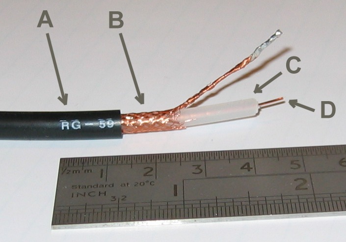
1.) The green line in Ceriatone's layout is the outer braid from the coax cable. You ground the braid at one end (and ONLY at one end) to create a shield. The green line is the braid.

The coax is used to it doesn't create interference in the signal path of the amp.
2.) No. Look at the layout again...the 16-ohm tap 27k resistor, that's the negative feedback loop.
The choke connects to the one side of the cap can at one end and then connects to "B" (the other side of the cap can)and the two 2-watt resistors (8.2K and 1K) at the board BESIDE toe negative feedback loop.
OT CT= Output transformer center-tap
The standby switch, the choke, the OT center tap, and pin 6 of the tremolo tube all connect to one 32uF cap. The other 32uF cap is connect to the other side of the choke, and the screens of the power tubes via wire "B".
Ceriatone has a dozen guts shots on their site (small pics, I admit)...
http://ceriatone.com/productSubPages/BSJTM45BB/BSJTM45BBCompleteAmp.htmHere is the pic of the footpedal jack...
in this amp the braid of the coax has been soldered to a red wire to runs to the ground lug directly in back of it (instead of the lug diagonally across).

They prepared it this way...


 to keep the forums alive.


 to keep the forums alive.